01 / Duct design
CFM where you need it
Read terminal and branch airflow alongside calculated duct diameters.
HVAC duct design software
Design HVAC ductwork with connected airflow, equal-friction sizing, fitting losses and critical-path pressure workflows. Start with MEPFlow's free duct sizer.
7 days free. Then $49 USD/month. Card required. Cancel anytime.
See MEPFlow in action
See connected terminals, automatic duct sizing, pressure review and 3D visualization working together on the same plan.
Try it yourself
Use prepared room loads, connect diffusers and size the duct system.
One form unlocks all four demos · No account or card needed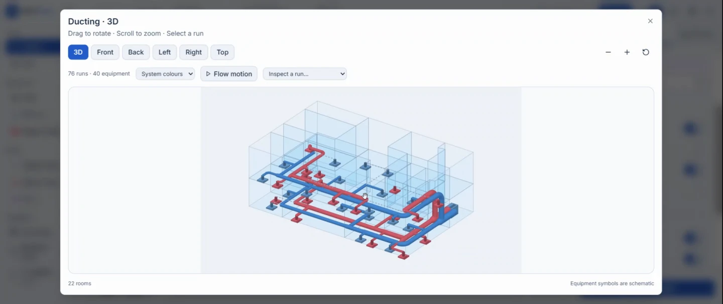
Use prepared room loads, connect diffusers and size the duct system.
Click the highlighted controls or use Got it.Follow the highlights. Use Back to revisit a step.
The connected workflow
A single duct diameter is only one part of a real HVAC design. MEPFlow is built around the system workflow: establish airflow, size sections, account for fittings and follow the pressure path that drives fan selection and coordination.
Inside the workflow
Follow terminal airflow, inspect the pressure calculation and review the same duct system in plan and 3D.
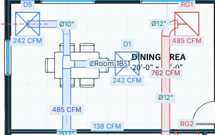
01 / Duct design
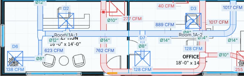
Read terminal and branch airflow alongside calculated duct diameters.
02 / Duct design
See estimated ESP, critical-route length and the contribution of ducts, elbows, junctions and terminals.
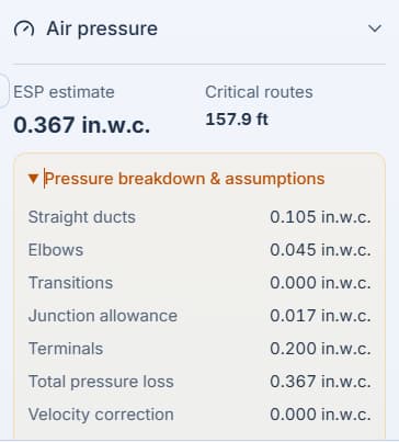
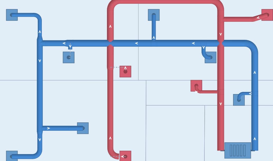
03 / Duct design
A simplified top view makes the supply and return branches easier to trace.
04 / Duct design
Review the duct system inside the room model and explain the routing to your team.
Watch the duct workflow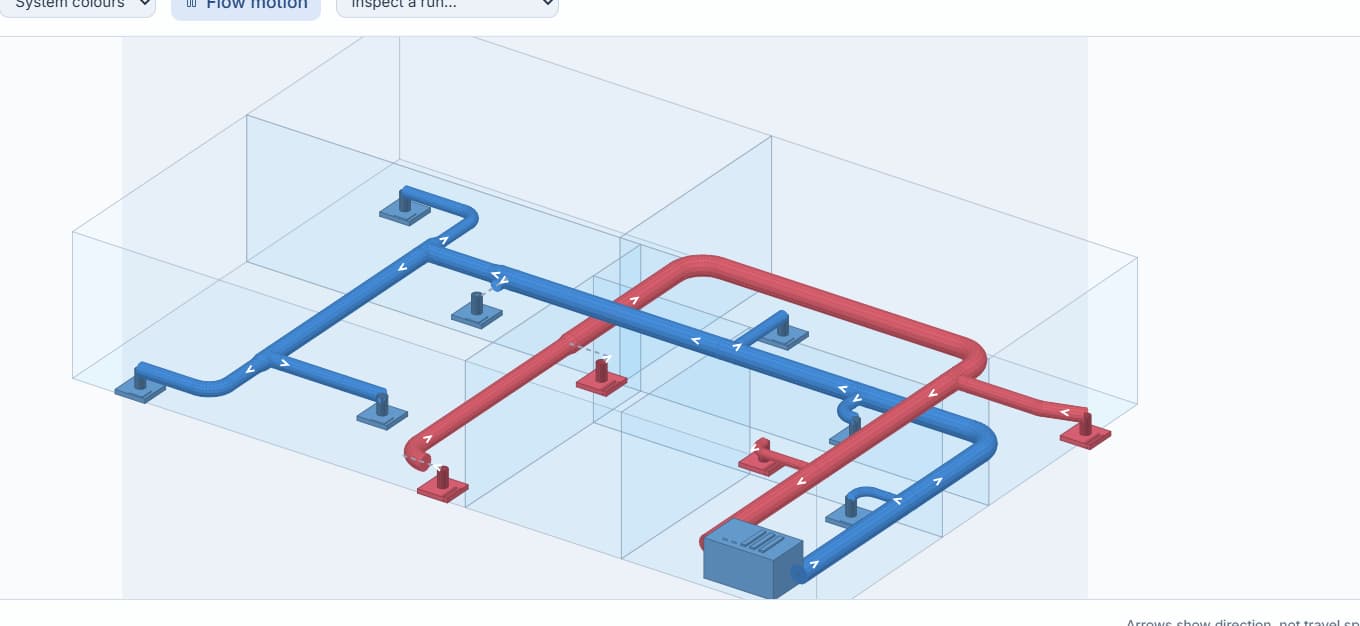
MEPFlow example project. Images show the relevant part of each workflow.
01 / System layout
Apply your calibrated PDF floor plan, place equipment and air terminals, and connect duct runs. Work with supply and return air and the available exhaust/outdoor-air services. Inspect endpoints and branch connectivity before relying on accumulated airflow.
See how to get started02 / Calculations & sizing
Establish outdoor-air and zone airflow requirements using the inputs and method appropriate to the space.
Apply equal-friction or velocity constraints to round and rectangular sections while reviewing practical limits.
Include straight-duct and fitting losses so pressure requirements are based on the system path, not an isolated section.
Useful duct software has to connect airflow, geometry and pressure rather than treating each section as an isolated ductulator calculation. MEPFlow keeps the major sizing checks visible so the designer can understand why a section or system result changes.
Duct sizing starts with a defensible airflow. Room loads, ventilation requirements and air-distribution decisions establish the CFM that each branch and main section must carry.
Equal-friction sizing provides a repeatable starting point, while velocity checks help identify sections that may create excessive pressure loss, noise or impractical dimensions.
The design workflow distinguishes actual rectangular cross-sectional area from equivalent-round relationships used for friction, so velocity and pressure calculations are based on the correct geometry.
Elbows, transitions, tees and other fittings can contribute a large share of system resistance. A complete pressure calculation therefore includes fitting losses rather than relying on straight-duct friction alone.
Fan pressure is governed by the path with the controlling total loss. MEPFlow is intended to carry section losses into a system-level critical-path review instead of stopping at duct size.
Terminal selection depends on airflow, face velocity, throw, pressure drop and acoustics. The duct workflow should remain coordinated with the diffuser and grille decisions at the end of each branch.
03 / Review your design
Use manual terminal airflow or supported room-load assignments as the design basis. After changing demands, geometry or connections, run Auto-size System and review the displayed results and warnings. A changed layout may need a new sizing pass; the software does not make every engineering decision automatically.
Review selected duct dimensions, airflow, velocity and available section/system pressure results. Export the drawing to a PDF overlay when an original PDF is available, or PNG. Use fan-pressure results with the equipment and fitting assumptions you have actually entered; they do not replace a manufacturer fan-curve or acoustic review.
Built for your work
Sizing each duct in a spreadsheet leaves a second job: keeping branch airflows, terminal connections and dimensions consistent on the drawing. A late terminal or route change can make the old size labels and pressure calculation misleading.
The MEPFlow community
Better tools start with the people who use them.
We’re gathering customer reviews from designers. Tell us how MEPFlow fits your work, what helps, and what you’d like to see next.
Solve airflow, friction rate, velocity or equivalent diameter for an individual duct section.
Related tools, software and engineering guides.
A few more details
Equal-friction sizing selects duct dimensions so straight sections have a consistent pressure-loss rate per unit length. The final system design still needs fitting losses, the critical path, acoustics and fan pressure.
Yes. The duct tools support round and rectangular geometry and distinguish actual rectangular velocity from the equivalent-round basis used for friction calculations.
Elbows, transitions, tees, dampers and other components add resistance beyond straight-duct friction. Their losses must be included on each path before the fan pressure requirement can be evaluated.
The critical path is the route from the fan to a terminal that produces the controlling total pressure loss after straight duct, fittings and equipment losses are considered.
No. It sizes an individual section. MEPFlow's broader workflow is intended to carry sizing into layouts, fitting losses and critical-path pressure calculations.
Yes. The duct sizing calculator supports both systems while keeping the underlying calculation consistent.
Have a question about your project? Talk to us
Automatic MEP sizing
Loads. Airflow. Ductwork. Pipework. Hydronics. Drainage. 3D. One connected engineering workflow.