Best Duct Design & Duct Sizing Software in 2026
Go beyond an isolated duct diameter. MEPFlow brings supply and return layouts, airflow, sizing and pressure-path review into a browser workspace—so the calculation stays close to the ductwork.
Published by MEPFlow · Methods and limitations · Primary references
Design your next duct layout in MEPFlow
Bring in a PDF, connect the air terminals and review your duct sizing in the browser. 30-day free trial, then $50 USD/month.
In this guide: jump to a step
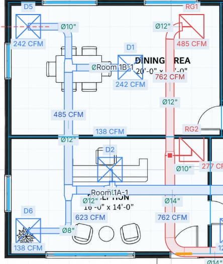
MEPFlow is our first choice for engineers who want to lay out and size ductwork directly over a floor plan in the browser. Supply and return branches, terminals, airflow inputs and sizing results belong in one design context, making it easier to see what each calculation describes.
A duct sizer is useful for a quick check. A complete design also needs routes, connections and a pressure-path review. This guide shows where MEPFlow brings those tasks together and when a BIM or specialist analysis tool belongs in the workflow.
The MEPFlow advantage
From airflow to a duct layout you can review
Lay out
Put branches and terminals in their actual floor-plan context.
Size
Use the entered airflow and supported sizing method to develop the network.
Review
Check velocities, sizes and the controlling pressure path together.
Explore the supported workflow in MEPFlow’s HVAC duct design software. Check the method, current scope and example outputs against your project requirements.
MEPFlow: best for duct layout and sizing in the browser
The reason to put MEPFlow first is the connection between the system you draw and the system you calculate. Build supply and return layouts over a PDF, connect terminals and review airflow and sizing inputs alongside the network.
That is a useful step beyond copying a diameter from a calculator into a separate drawing. When a branch changes, the project gives you a visible route to review. Run sizing, inspect the resulting sizes and pressure path, and resolve warnings while the layout is in front of you.
The duct design workspace is available in the 30-day free trial. For a quick first check, the free duct sizer works without an account. Move into the workspace when the job needs connected branches and terminals.
Use a dedicated tool when the brief specifically requires acoustic analysis, specialist balancing or a native BIM deliverable. MEPFlow’s focus here is the supported floor-plan, airflow and sizing workflow.
- Draw supply and return routes with diffusers, grilles and connected airflow demands.
- Review duct sizes and design inputs against the floor plan.
- Keep sizing and pressure-path review close to the network being designed.
- Begin with a free calculator or start a full layout during the 30-day free trial.
Compare the type of duct tool first
A duct calculator, a network-sizing program and a BIM authoring application may all be sold as duct design software. Their outputs differ. Use the table to choose the category before comparing licenses or demonstrations.
| Tool | Best for | Design workflow | Selection notes |
|---|---|---|---|
| MEPFlow | Best for connected browser-based duct design | Supply/return layouts, airflow, sizing and pressure-path review | 30-day free trial, then $50 USD/month; review fitting inputs, size locks and results after sizing |
| MagiCAD Ventilation | Ventilation calculations within the model | Supported CAD/BIM environment and calculation reports | Confirm host, localization and calculation options |
| Autodesk Revit | Duct systems within coordinated building documentation | BIM model and project documentation | Test the exact native or add-on analysis workflow |
| Trimble Nova | Ventilation networks with integrated calculation | Independent CAD/CAE workflow | Confirm calculation module and required exchange |
| VariTrane Duct Designer | Dedicated supply sizing and fitting checks | Duct Configurator, Ductulator and Fitting Loss Calculator | Check current licensing and support lifecycle |
| MEPFlow free duct sizer | Individual round/rectangular section checks | Browser calculator without signup | A section result is not a complete system-pressure calculation |
| ASHRAE Duct Fitting Database Lite | Selected fitting pressure-loss checks | Mobile calculation tool | Selected fitting scope; not a complete design platform |
Design your next duct layout in MEPFlow
Bring in a PDF, connect the air terminals and review your duct sizing in the browser. 30-day free trial, then $50 USD/month.
Start a duct designWhat each shortlist option contributes
MagiCAD’s ventilation calculations include sizing, balancing, pressure loss and sound analysis, with calculation reports. If your brief includes acoustic evaluation or balancing inside the model, those are meaningful reasons to investigate this specialist workflow.
Revit places the duct system within the wider BIM documentation process. Trimble Nova offers schematic and 3D ventilation networks with integrated calculations. The choice between those environments depends partly on the receiving model and office process, not just the duct-sizing result.
VariTrane Duct Designer includes a supply-network configurator, a ductulator and a fitting-loss calculator. Trane’s current page also points to lifecycle information. Confirm availability and support before standardizing a new office process around an older installed tool.
ASHRAE’s Duct Fitting Database Lite covers selected fitting pressure losses. It is useful as a bounded fitting check, not a substitute for a complete network model. Similarly, the free MEPFlow duct sizer helps evaluate an individual section without implying that the whole fan-pressure path has been solved.
A three-terminal trial that reveals more than a demo
Create an illustrative supply branch serving terminals of 200, 300 and 500 CFM. The common upstream section carries 1,000 CFM if all three demands occur together and leakage is excluded. After a branch splits, each downstream section should carry only the demand assigned to that route.
Change the 300 CFM terminal to 450 CFM. The common upstream demand becomes 1,150 CFM under the same assumptions. Check that the changed airflow reaches the correct sections and that the sizing action is clear. Size limits or the selected method may legitimately retain a duct size.
Next move the 500 CFM terminal and lengthen its route. This is a geometry change without a demand change. Check which losses and pressure-path results change. If the new route becomes controlling, the fan-pressure assessment should reflect the revised network.
Finally disconnect and reconnect one terminal deliberately in a disposable trial project. Observe the warning and calculation behavior. Save, reopen and compare the displayed layout with the report or available output. A program that performs the first straight-section calculation well can still require careful review of these editing cases.
Engineering visual
See what one airflow change affects
Illustrative branch with simultaneous terminal demands and no leakage.
Original terminals
200 + 300 + 500
The common upstream section carries 1,000 CFM.
Revised terminal
300 → 450 CFM
Change the middle terminal demand; retain the other two.
Revised upstream flow
1,150 CFM
Rerun sizing and inspect the affected sizes and pressure path.
| Trial action | Expected engineering relationship | Inspect |
|---|---|---|
| Initial 200 + 300 + 500 CFM | 1,000 CFM upstream under the stated basis | Branch membership and airflow units |
| Change 300 to 450 CFM | 1,150 CFM upstream | Affected sections and sizing action |
| Lengthen one route | Flow can stay constant while losses change | Lengths, fittings and controlling path |
| Lock one duct size | Manual constraint remains visible | Velocity or pressure consequence |
| Save and reopen | Same accepted design state is retained | Connections, inputs, warnings and output revision |
Sizing method: ask what the program is solving
Equal-friction sizing uses a selected friction-rate basis to size runs, subject to practical constraints. A velocity limit places a different constraint on the design. Static-regain workflows address pressure behavior in a different way again. The useful question is which method the selected tool and module actually implements—not which label sounds most advanced.
For an equal-friction workflow, inspect the entered rate and units, available standard sizes, round or rectangular geometry and any aspect-ratio limit. Then review actual velocities. An acceptable friction rate does not by itself prove that terminal noise, available ceiling depth or fan selection is acceptable.
The duct sizing engineering guide explains the relationship between airflow, size and pressure loss. Use that reasoning as a check on the trial. Do not compare two software outputs until you have aligned the input basis and constraints.
If a candidate does not document the required method, ask the vendor to demonstrate it. Avoid converting a missing description into an unsupported claim that a competitor cannot perform the calculation.
Pressure-drop software must expose the whole path
A straight-duct friction number is only one contribution to system resistance. A useful review follows a complete source-to-terminal route, with the applicable straight lengths, fittings and devices. The route with the greatest resistance need not be the physically longest.
Ask how the program treats transitions, branches, elbows, terminal losses and equipment pressure drops. Determine whether device values are calculated, entered by the designer or omitted from the scope. Check that losses are neither missing nor counted twice across adjoining sections.
A pressure figure should have a clear location and meaning. Static pressure, total pressure, friction rate per unit length and the pressure loss of a particular fitting are not interchangeable report columns. Have the demonstrator explain one route using the actual report headings.
Review the critical-path pressure-drop example before comparing tools. Keep the fan selection and manufacturer performance checks connected to the accepted system calculation, including the operating conditions and allowances used by the project.
Compare drawings, reports and the revision handoff
If the client needs a coordinated BIM model, test that handoff early. A PDF diagram, a CAD drawing and a native BIM system can all look convincing in a presentation but carry different data. Open a real export in the receiving software and inspect identifiers, connectivity and units where those are required.
For an engineering report, look for traceable section names, terminal demands, sizes, method settings and the controlling path. The reviewer should be able to match a row back to the layout. If the output is mainly a screen result, decide whether that satisfies your office record requirements.
Collaboration is another separate test. Ask what sharing actually means: a common file, a published model, a review workflow or simultaneous editing. Browser access alone does not establish any of those capabilities. This guide does not assume an undocumented collaboration feature.
Have a second intended user review the revised example without help from the demonstrator. That reveals whether the workflow is understandable in your office, which is more useful than assigning a generic easy-to-learn score.
Choose a duct workflow for the work you repeat
For a floor-plan-based duct network, start with MEPFlow. It puts the route, terminal demand and sizing review in the same workspace, which is exactly where an isolated duct calculator stops being enough.
Try the three-terminal revision above on your own layout. Inspect the upstream airflow, selected sizes and pressure path after sizing. Keep a small independent check as part of your normal design review.
Use MagiCAD, Revit or another appropriate model environment when the contract calls for a native BIM workflow; add a documented acoustic or balancing tool when required. For the everyday layout-and-sizing task, explore MEPFlow duct design or watch the duct demonstration.
Frequently asked questions
What is the difference between duct design software and a duct sizer?
A duct sizer typically evaluates a section using inputs such as airflow, size, friction and velocity. A design workflow also represents the network, its connections and the required outputs. Check whether the tool calculates complete pressure paths or only individual components.
Can a ductulator calculate total fan static pressure?
A section-sizing result does not establish total system pressure. You need a complete path assessment with the applicable straight duct, fittings and device losses, interpreted using the fan and system pressure definitions for the project.
Which duct software is best for BIM projects?
Start with the contractual model requirement. Revit-based work may favor native Revit functions with a verified specialist tool where needed; Nova offers a separate CAD/CAE environment. Test the actual calculation and exchange rather than assuming all BIM workflows are interchangeable.
How does MEPFlow handle duct design changes?
MEPFlow keeps the connected duct layout and its supported calculations in one workspace. After editing airflow or geometry, run sizing and review the affected sizes, pressure paths and warnings. This keeps the revision tied to the actual network.
Is there free duct sizing software?
MEPFlow has a free browser duct sizer that works without signup, and the design platform currently offers a 30-day free trial, followed by $50 USD/month. They serve different scopes: a single-section calculation and a supported connected project workflow.
Continue the engineering workflow
Design your next duct layout in MEPFlow
Bring in a PDF, connect the air terminals and review your duct sizing in the browser. 30-day free trial, then $50 USD/month.
Start a duct designPrimary references
Published by the MEPFlow team. Product information was checked against the linked first-party sources on 15 September 2026. Compare the edition, calculation method and deliverables required for your project.