Best HVAC Load Calculation Software in 2026: HAP, TRACE, IESVE and More
Make the floor plan part of the load calculation. MEPFlow combines room geometry, RTS design-day cooling, heating loads and reviewable results in a browser workflow you can try free for 30 days, then $50 USD/month.
Published by MEPFlow · Methods and limitations · Primary references
Calculate your next room loads in MEPFlow
Start from a PDF floor plan and develop a room-by-room load model. Review the sample first or start a 30-day free trial, then continue for $50 USD/month.
In this guide: jump to a step
MEPFlow is our first choice for engineers who want room-by-room peak loads from a floor plan without a desktop installation. Trace the spaces, enter the envelope and design conditions, and review heating, cooling and coincident results in the browser.
The advantage is a clear path from geometry to engineering results, with a calculation-report PDF and a load schedule for review. This guide compares that design-day workflow with HAP, TRACE 3D Plus, IESVE and DesignBuilder, which also address wider system or building-performance requirements.
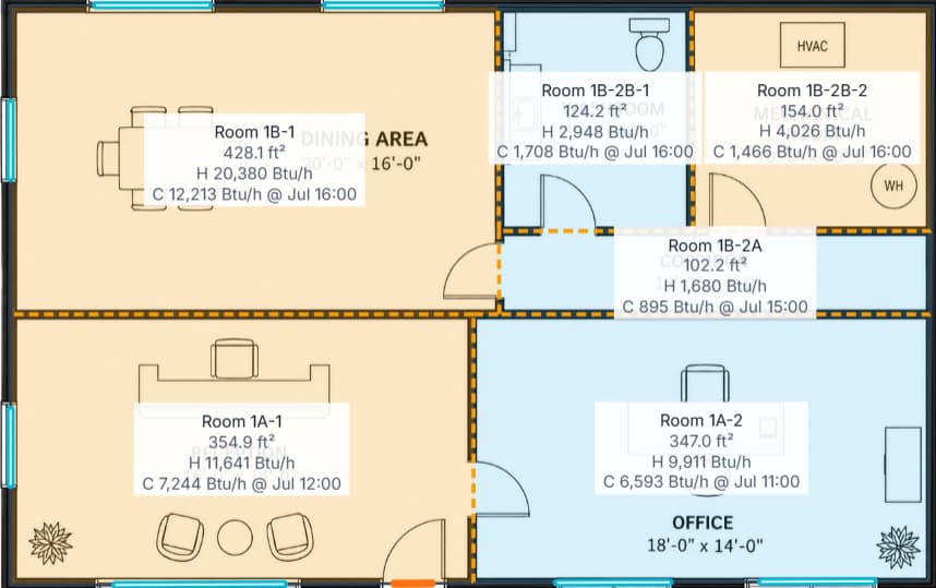
The MEPFlow advantage
A direct route from floor plan to load review
Room geometry
Trace spaces and review the boundaries that drive the calculation.
Design inputs
Keep constructions, glazing, weather and gains explicit.
Reviewable results
Check room loads, coincident results and the calculation report.
Explore the supported workflow in MEPFlow’s HVAC load calculation software. Check the method, current scope and example outputs against your project requirements.
MEPFlow: best for floor-plan-based load calculations in the browser
MEPFlow makes the plan a working part of the load model. Upload and calibrate the PDF, trace rooms, assign constructions and glazing, and enter the design conditions and internal gains. The room boundaries and calculation inputs are reviewed in the same workspace.
The Loads workflow uses RTS design-day cooling and steady-state winter heat loss. Review room results, heating and cooling components, airflow assumptions and the coincident block result. A report PDF and load schedule CSV provide a way to carry the calculation into the review process.
This is why MEPFlow leads our shortlist for the floor-plan-to-peak-load task: the geometry, assumptions and results remain close together, and you can begin in the 30-day free trial. See the Loads workspace and the worked two-room example before starting your own model.
For annual energy modeling or detailed HVAC system simulation, use the appropriate analytical platform below. MEPFlow’s recommendation here is for its stated design-day load workflow; required methods and project deliverables still determine the final toolset.
- Trace room geometry directly over a calibrated PDF floor plan.
- Assign envelope, glazing, orientation, internal gains and design conditions.
- Review room peaks alongside the coincident block result.
- Inspect the calculation-report PDF and export the load schedule CSV.
Compare the five workflows
Start with the quantity and deliverable you need. A room cooling load, a system coil load, a coincident building peak and annual energy use answer different questions. The following table identifies where each candidate enters that decision.
| Software | Best for / analytical role | Working model | Selection notes |
|---|---|---|---|
| MEPFlow | Best for browser-based floor-plan-to-peak-load work | RTS cooling, winter heating, room/coincident results | Start Free Trial; review the Loads report PDF and schedule CSV |
| Carrier HAP | Commercial loads, system sizing and energy modeling | Graphical building input and system-based analysis | Do we need dedicated commercial HVAC sizing and analysis reports? |
| Trane TRACE 3D Plus | HVAC design and analysis using EnergyPlus | Building and system analysis workflow | Does the selected edition provide our required system and energy deliverables? |
| IES Virtual Environment | Loads, HVAC and broader building-performance simulation | Analytical building/system applications | Do we need detailed performance analysis beyond peak sizing? |
| DesignBuilder | EnergyPlus-based simulation with HVAC modules | 3D analytical building and system model | Do we need to study building and system performance together? |
Calculate your next room loads in MEPFlow
Start from a PDF floor plan and develop a room-by-room load model. Review the sample first or start a 30-day free trial, then continue for $50 USD/month.
Start a load calculationCarrier HAP: dedicated commercial HVAC analysis
Carrier HAP uses the ASHRAE Heat Balance method for building loads and provides system-based sizing, graphical building input and energy modeling. Carrier describes room/zone/system airflow calculations and reports tailored to the selected system. That is a substantial analytical scope, not merely a room-area calculator.
HAP belongs on the shortlist when the office needs commercial load-to-system analysis and its associated reporting. Evaluate a representative system rather than comparing only the room sensible-load total. Confirm the report needed for coils, airflows and the selected HVAC arrangement.
During migration, keep the accepted model available as a reference. A new tool may use different defaults, boundary assumptions or sizing procedures. Document the reason for differences before treating one answer as more accurate. Include your reviewer’s report requirements in the decision.
TRACE 3D Plus: evaluate the selected product and reports
TRACE 3D Plus uses EnergyPlus and offers room heating/cooling and system-component reporting. Trane also documents library exchange and support resources. Confirm the selected product edition, required outputs and current migration/support information.
An existing TRACE workflow can include more than peak loads. Ask which analysis steps your team actually relies on and verify that any proposed replacement covers them. Reproducing one room total does not prove that the system model, energy alternatives or reporting process has migrated.
For a clean comparison, define the same building conditions and system boundary. Then inspect the point at which room loads become system sizing inputs. Keep differences in diversity, outdoor air, fan contributions and operating assumptions visible to the reviewer.
IESVE and DesignBuilder: when building performance drives the choice
IESVE offers loads and equipment-sizing workflows within a wider building-performance platform. Its ApacheHVAC application addresses component-based HVAC design, sizing and modeling. It is a stronger candidate than a peak-only layout tool when detailed system and building analysis are central requirements.
DesignBuilder provides a 3D modeling environment with EnergyPlus simulation and HVAC modules. It is relevant when the team wants to evaluate the building and system together, rather than stop after a design-day room calculation. Confirm the exact package and outputs required for the project.
The additional analytical scope has a practical implication: the model must contain the information needed for those studies. Assign responsibility for schedules, controls, system definitions and operating assumptions. Detailed performance studies also need the corresponding schedules, controls and system definitions.
For both products, confirm that the selected package supports the method and deliverable accepted for your project.
Compare room peaks, coincident peaks and system loads
Suppose one room peaks at 10 kW in the morning and another peaks at 8 kW later in the day. Adding their separate maxima produces 18 kW. That sum does not tell you their simultaneous peak. A coincident result requires the loads at matching times and under the defined design cases.
A system coil may have additional loads or a different boundary from the sum of rooms. Outdoor air treatment, fan effects and the system arrangement can matter. Ask the program to show which contributions belong in each result and how the design condition was selected.
Heating and cooling inputs should also remain distinct. The winter condition, internal gains assumed available during heating design, summer design cases and ventilation operation must be intentional. The peak-load engineering guide explains these input decisions.
Engineering visual
Room peaks and the building peak answer different questions
Room A peaks at 10 kW
Use the room result for its own design review.
Room B peaks at 8 kW
Its maximum may occur at a different hour.
Coincident result
Sum the rooms at the same hour, then find the highest combined value.
MEPFlow review
Inspect the room results and the coincident block result together.
| Result | What it addresses | What it does not establish alone |
|---|---|---|
| Room heating loss | Required winter heat replacement under the stated basis | Seasonal energy use or selected equipment capacity |
| Room cooling peak | Maximum room cooling demand for evaluated cases | Simultaneous sum across all rooms |
| Coincident room/building peak | Loads at matching times under evaluated cases | Every system coil or plant sizing contribution |
| System sizing result | The defined HVAC system boundary | Final equipment suitability at every condition |
| Annual energy | Operation across a modeled year | A substitute for a checked peak-design procedure |
Use one common input schedule for every trial
Most software comparisons fail before the calculation starts because the two models do not describe the same building. Prepare a common schedule containing room geometry, exterior surfaces, adjacent conditions, constructions, glazing, orientation, weather basis, setpoints, people, lighting, equipment and outdoor-air assumptions.
Record units explicitly. Review glazing orientation and area before adjusting a construction to make two outputs agree. Check which walls are external, internal or adjacent to another thermal condition. A wrong boundary can have more effect than the difference between accepted calculation methods.
Create an inputs review before the results review. Have the engineer responsible for the building assumptions sign off that the candidate model represents the intended case. Then compare component breakdowns, timing and totals. A component check is more diagnostic than a single percentage difference at building level.
Avoid mixing preliminary values and final selections without labeling them. A trial can use assumptions, but the accepted design must identify which inputs were subsequently replaced and which outputs were recalculated.
See the result of that review process in MEPFlow’s actual generated sample report. The preview below uses the published two-room teaching example, so you can inspect the method, assumptions and room schedule before creating an account.
Make a solar and zoning revision during evaluation
Choose a room with glazing and change its orientation or glazing input while holding other conditions fixed. Review the cooling breakdown and peak timing. This exposes whether the result reflects the intended change, without asserting that every method must produce the same hourly profile.
Next change the grouping of rooms into systems or zones where that feature is part of the candidate’s scope. Review which totals represent separate room maxima and which represent simultaneous conditions. If the tool does not perform that system analysis, record the handoff to the software that does.
Finally change a winter design input and verify the heating calculation separately. Save and reopen, then generate the required report. The report should let another engineer understand the input basis, warnings and selected results.
This is an evaluation protocol, not a published validation of any vendor. For MEPFlow, use the building heat-loss guide and cooling-load guide as independent explanations of the relevant quantities.
Choosing an alternative to HAP, TRACE or IESVE
If your next task is a design-day room-load model from a PDF, start with MEPFlow. Its browser workflow gives you a clear place to connect geometry, assumptions and results, with a 30-day free trial and a public example you can inspect first.
If you are replacing HAP, TRACE or IESVE, identify which outputs the existing model supplies. Keep the analytical platform for annual energy, detailed system modeling or a required procedure outside MEPFlow’s scope. A focused Loads workflow can also sit alongside an established specialist tool.
Use the sample project to see the calculation record, then bring a known portion of your own plan into the MEPFlow Loads workspace. The HVAC software guide shows how the supported air- and water-side workflows fit around the load calculation.
Frequently asked questions
Which HVAC load software is best for commercial buildings?
For a floor-plan-based commercial room-load workflow in the browser, MEPFlow is our first recommendation. HAP, TRACE 3D Plus, IESVE and DesignBuilder remain relevant when the project also requires their particular system-sizing, annual-analysis or simulation outputs.
When is MEPFlow a good alternative to HAP or TRACE?
MEPFlow is worth starting with when your requirement is its supported design-day room loads, a floor-plan workflow and reviewable results. If your HAP or TRACE project also depends on annual energy or detailed system analysis, retain or replace those capabilities separately.
Are RTS and Heat Balance outputs supposed to be identical?
Do not assume identical results. Before comparing methods, align geometry, constructions, weather, gains, schedules and system boundaries. Investigate component differences and peak timing rather than judging only the final total.
Is this a Manual J software comparison?
No. It focuses on building and commercial HVAC load-analysis workflows. If a residential project requires Manual J or another named procedure, verify a tool’s current acceptance for that exact requirement rather than assuming equivalence.
Can I see a MEPFlow load report before signing up?
Yes. The public sample project includes the teaching plan, reference inputs and an actual generated calculation-report PDF. You can inspect the room schedule and assumptions before opening a 30-day trial account.
Continue the engineering workflow
Calculate your next room loads in MEPFlow
Start from a PDF floor plan and develop a room-by-room load model. Review the sample first or start a 30-day free trial, then continue for $50 USD/month.
Start a load calculationPrimary references
Published by the MEPFlow team. Product information was checked against the linked first-party sources on 15 September 2026. Compare the edition, calculation method and deliverables required for your project.