01 / Heating & cooling loads
Start with the load in each space
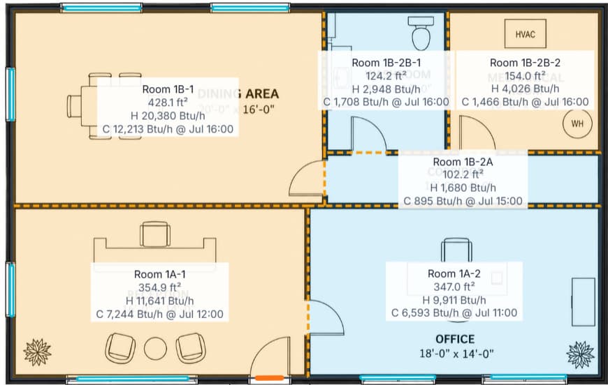
Review room area and heating and cooling demand before developing the air-distribution system.
Explore room loads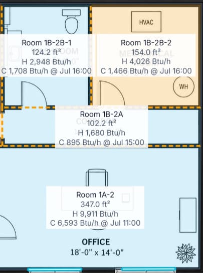
HVAC design software
Design HVAC systems in your browser: calculate room-by-room heating and cooling loads, carry demand into duct sizing and pressure review, lay out hydronic piping, and inspect systems in 3D over a shared PDF floor plan.
30 days free. Then $50 USD/month. No credit card required.
The connected workflow
Use MEPFlow for the mechanical design sequence from room demand to air- and water-distribution layouts. The same project can move from Peak Loads into Ducting, Hydronics or Underfloor Heating, while each workflow keeps its own engineering inputs, sizing controls, results and review steps visible.
Inside the workflow
Follow the air-side workflow from the load model to airflow, pressure and spatial review.
01 / Heating & cooling loads
Review room area and heating and cooling demand before developing the air-distribution system.
Explore room loads02 / Duct design
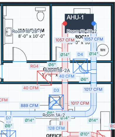
Supply diffusers, return grilles and connected branches keep the airflow visible on the drawing.
Explore duct sizing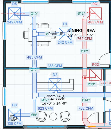
03 / Duct design
Inspect the ESP estimate, critical-route length and component losses in one focused view.
Review duct pressure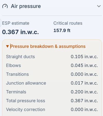
04 / Duct design
Inspect supply and return runs in relation to the room model.
Watch the duct workflow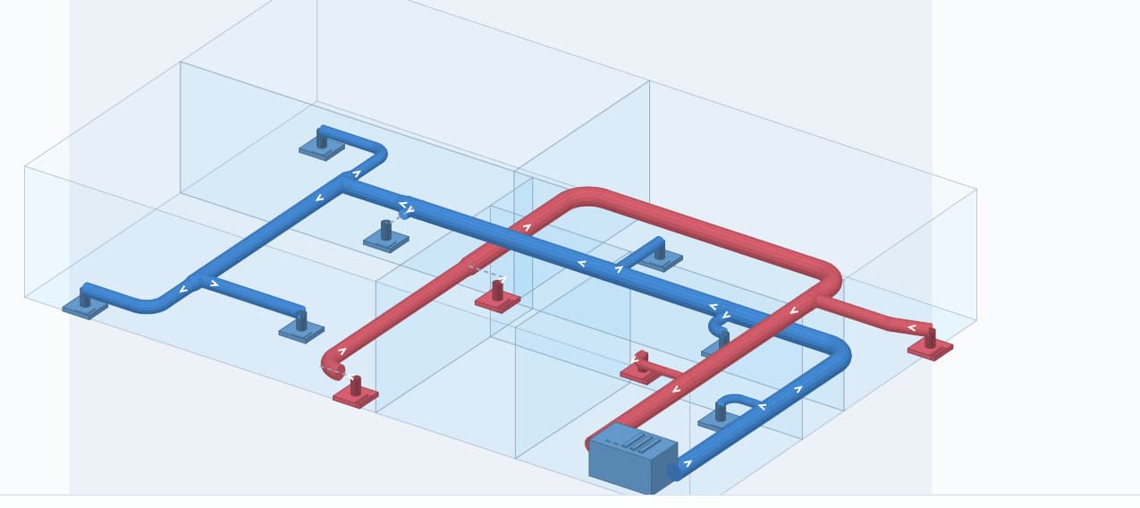
MEPFlow example project. Images show the relevant part of each workflow.
01 / System layout
Begin with the project floor plan and shared scale. Use Loads for room geometry and design conditions, Ducting for the air-distribution layout, and Hydronics when heating or cooling is delivered through a water circuit. Use Underfloor Heating for radiant floor loops, heat-balance review and manifold results. The dedicated workflow pages below explain each module.
See how to get started02 / Calculations & sizing
Trace rooms, set envelope and weather inputs, and calculate heating and cooling demand. Distinguish a room peak from the coincident block peak.
Set supply airflow, ventilation and exhaust requirements. Choose manual inputs or supported space-demand assignments and check the receiving terminals or equipment.
Connect ducts or pipes, apply the module sizing action and review dimensions, flow, pressure information and warnings.
Load calculations, ventilation and distribution sizing answer different design questions. Keep their units and assumptions clear as you move between them.
Estimate the design heating requirement from the exposed envelope, indoor/outdoor temperature difference, infiltration and outdoor-air inputs.
Account for envelope, solar, people, lighting, equipment and moisture loads. The Loads workflow uses RTS cooling with steady-state winter heat loss.
Use the separate public ventilation and exhaust calculators for their stated scope. Breathing-zone outdoor air is not automatically total supply airflow or a complete multi-zone ventilation design.
Ducting carries selected airflow through the network. Hydronics relates equipment duty and design temperature difference to water flow, pipe-size and head-loss review.
03 / Review your design
Establish room demand before reviewing the supported air-terminal and equipment assignments. Keep manual overrides visible, recalculate changed loads and rerun system sizing when needed. Ventilation, supply airflow and exhaust have different purposes; one quantity does not automatically substitute for another.
Review room/block loads, duct sizing and water-side flow in their respective module results. Loads supplies a calculation-report PDF and schedule CSV; duct and hydronic drawings export as PDF overlays or PNG. Annual energy use, dynamic plant simulation and whole-building compliance assessment need the appropriate specialist tools.
Built for your work
HVAC design spans several decisions: how much heat a space gains or loses, how much supply and outdoor air it needs, how that air is distributed, and how water-side equipment is connected. Solving them in separate files makes a design change harder to follow.
The MEPFlow community
Better tools start with the people who use them.
We’re gathering customer reviews from designers. Tell us how MEPFlow fits your work, what helps, and what you’d like to see next.
Check people-plus-area breathing-zone outdoor airflow.
Related tools, software and engineering guides.
A few more details
It supports load calculations, system layout, airflow or water-flow calculations, and distribution sizing. MEPFlow connects these mechanical workflows inside a browser project; the dedicated module pages identify its supported methods and outputs.
The Loads module calculates steady-state design heating loss and RTS design-day cooling loads, including supported envelope, solar and internal-gain inputs. Heat gain and cooling load are related but differ because of thermal storage and time response.
Yes. Upload a PDF drawing, choose its page/floor placement and establish scale before tracing spaces or routing systems. The PDF is a drawing background, not an automatically recognized building model.
Yes. The public ventilation, exhaust and airflow calculators work without signup. Review each tool’s scope; an outdoor-air result does not by itself determine total supply airflow or complete an air-balance design.
It is an option for the supported browser-based design and sizing tasks. HAP and IESVE also address specialist simulation and system-analysis workflows. Choose by the required method and deliverable rather than assuming the tools are interchangeable.
No native Revit or IFC export is advertised. The current documented outputs include Loads reports/schedules and PDF-overlay or PNG drawings for the established distribution modules.
Have a question about your project? Talk to us
Automatic MEP sizing
Loads. Airflow. Ductwork. Pipework. Hydronics. Drainage. 3D. One connected engineering workflow.