HVAC Duct Pressure Drop: Calculate the Critical Path
The longest duct route is not automatically the worst route. Add every straight, fitting and component loss along each complete fan-to-terminal path.
ΔP = duct + fittings + devices
HVAC Duct Pressure Drop: Calculate the Critical Path
Original MEPFlow engineering guide
Prepared to help mechanical designers understand the calculation, assumptions and review checks. Examples are original and educational; verify the governing code, project criteria and equipment data before using a result for construction or permit documents.
Duct pressure drop is the pressure energy lost as air moves through straight duct, fittings, dampers, filters, coils, terminals and equipment connections. Fan external static pressure should come from a complete system path, not from a friction rate multiplied by total duct length.
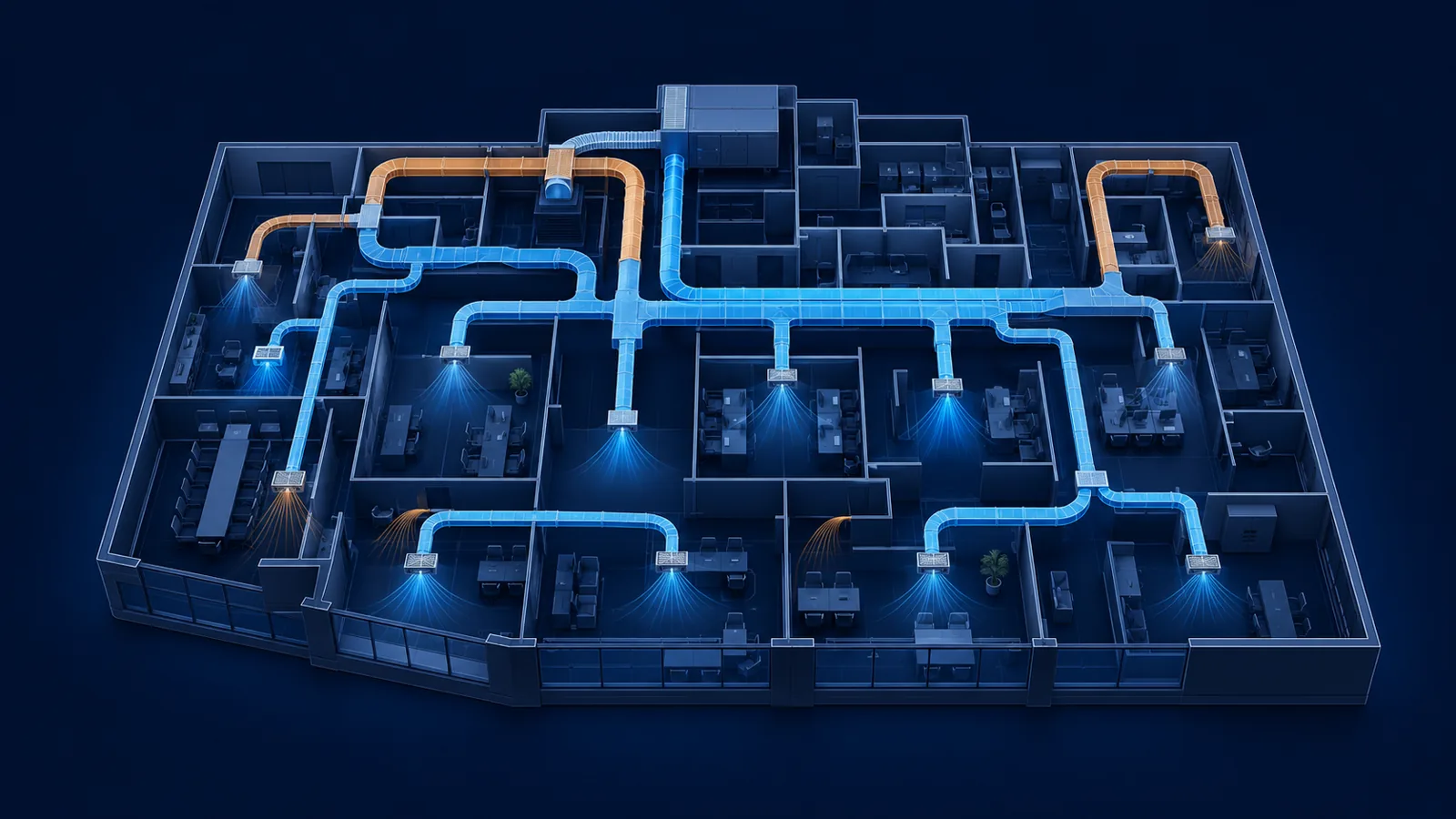
A connected model makes path analysis practical because every segment knows its airflow, size, upstream and downstream relationships. The critical path is the route requiring the greatest total pressure—not necessarily the route with the greatest physical length.
Build the path total
Straight-duct loss is commonly calculated from friction rate and actual length. Fitting loss can be represented with loss coefficients or equivalent length. Equipment and terminal losses come from selected data at the design airflow.
Use one consistent method and avoid counting the same fitting as both a coefficient and an equivalent length.
Engineering visual
A complete fan-to-terminal pressure path
Fan/AHU
Start
Available pressure at design airflow
Duct + fittings
Distributed losses
Straight friction, elbows, tees and transitions
Terminal
End
Damper, diffuser or grille pressure requirement
ΔPpath = Σ(ΔPstraight + ΔPfittings + ΔPcomponents)
Calculate the sum for every complete path. The path with the largest required pressure governs the fan pressure basis, subject to the system arrangement.
Straight-duct friction
Equal-friction sizing targets a similar straight-duct friction rate across the system. It is a useful first pass, but equal friction does not produce equal path losses because lengths and fittings differ.
Density, roughness, hydraulic diameter and velocity affect friction. Flexible duct, internally lined duct and rough transitions may require different data from smooth galvanized duct.
Fittings and velocity pressure
A loss coefficient expresses fitting pressure loss relative to velocity pressure. Geometry matters: elbow radius, tee flow split, area ratio and upstream conditions can materially change the coefficient.
High-velocity fittings deserve attention because velocity pressure rises with the square of velocity. Closely spaced fittings can also behave differently from isolated catalogue fittings.
ΔPfitting = C × Pv
C is the fitting loss coefficient and Pv is velocity pressure at the reference section defined by the adopted data source.
Find and review the critical path
Calculate every route from fan to supply terminal and, where applicable, the return path back to the fan. A short branch with a restrictive control damper may exceed a longer, larger branch.
1. Confirm segment airflow
Accumulate all downstream terminal flows through the network.
2. Confirm sizes and materials
Use actual internal dimensions and the intended roughness basis.
3. Assign fitting data
Match geometry, flow split and reference velocity.
4. Add component losses
Include coils, filters, dampers, louvers and terminals at design airflow.
5. Compare complete paths
Identify the largest total and document the fan selection basis.
Static pressure mistakes to avoid
Pressure calculations fail most often through missing scope rather than difficult arithmetic.
- Using only the physically longest path.
- Applying one fitting coefficient to a different geometry.
- Leaving dirty-filter or selected-coil pressure out of the fan basis.
- Adding manufacturer losses at an airflow different from the scheduled design point.
- Ignoring return or exhaust-side losses that the same fan must overcome.
- Treating balancing-damper pressure as free rather than part of fan energy.
Worked critical-path pressure calculation
Take a supply path from an air-handling unit to a remote diffuser. The path contains 120 ft of main and branch duct at an average straight-duct friction rate of 0.08 in. w.g. per 100 ft, giving 0.096 in. w.g. The fittings include two elbows at 0.08 each, a tee path at 0.12 and a transition at 0.04, for 0.32 in. w.g. The volume-control damper contributes 0.10, and the selected diffuser contributes 0.08 at design airflow. The supply path subtotal is therefore about 0.596 in. w.g.
The fan does not stop at the diffuser. A complete external-static calculation may also include the return-air path, return grille, return duct fittings, outside-air path, accessories and any devices outside the manufacturer's stated unit casing pressure. Internal coils and filters may already be included in a packaged-unit rating—or may need to be added—so the equipment selection definition must be read carefully. Adding a 0.45 in. w.g. return path to the example produces roughly 1.05 in. w.g. before contingency or future filter loading.
Another terminal may be farther away but use larger, straighter duct and therefore have less loss. The critical path is the path with the greatest total pressure requirement, not automatically the longest geometric distance. Calculate every plausible end path after the network is sized, then highlight the controlling path and the next few near-critical paths for review.
| Path component | Pressure loss |
|---|---|
| 120 ft straight duct | 0.096 in. w.g. |
| Elbows, tee and transition | 0.320 in. w.g. |
| Volume-control damper | 0.100 in. w.g. |
| Supply diffuser | 0.080 in. w.g. |
| Supply path subtotal | 0.596 in. w.g. |
Hand the pressure budget to fan selection correctly
Fan selection needs airflow and the correct pressure definition at the required operating condition. External static pressure, total static pressure and total pressure are not interchangeable. The scheduled value should match how the manufacturer tests and publishes the equipment. If an accessory is inside the selected unit but also added to the external calculation, it is counted twice; if a field-installed filter or heat exchanger is outside the published allowance and omitted, the fan is undersized.
Pressure losses change with approximately the square of airflow for many system components. A design that later increases airflow by 10 percent can see roughly a 21 percent rise in those losses. Dirty filters, coil fouling, balancing damper position and diversity can also move the operating point. A reasonable allowance should be tied to known uncertainty rather than an arbitrary blanket percentage that hides incomplete takeoff.
After selecting the fan, place its curve against the calculated system curve and review efficiency, motor power, sound and controllability. Variable-speed operation should maintain required pressure at part load without excessive reset or unstable terminal control. Commissioning should compare measured fan pressure and critical-path terminal performance with the design model so large discrepancies can be traced to construction, balancing or model assumptions.
- State whether scheduled pressure is external static, total static or total pressure.
- Identify which filters, coils, dampers and accessories are inside versus outside the equipment rating.
- Check clean and design-final filter conditions where applicable.
- Keep fitting loss data and assumed coefficients with the path report.
- Recalculate after major routing, airflow or duct-size changes; the critical path can move.
Frequently asked questions
What is the duct critical path?
It is the complete airflow route with the greatest total pressure requirement after straight duct, fittings, components and terminals are included.
Is the longest duct run always the critical path?
No. Fittings, velocity, dampers and components can make a shorter route require more pressure.
Does equal-friction sizing equalize path pressure?
No. It targets straight-duct friction rate; different path lengths and fitting losses still create different totals.
Primary references
Use the edition and method accepted for your project. These authoritative resources provide further context; this article is educational and is not a code-compliance determination.