How to Size an Intake or Exhaust Louver: Free Area, Velocity and Pressure Drop
A practical workflow that separates gross face area from free area and carries a louver estimate through airflow, pressure-drop and rain-performance checks.
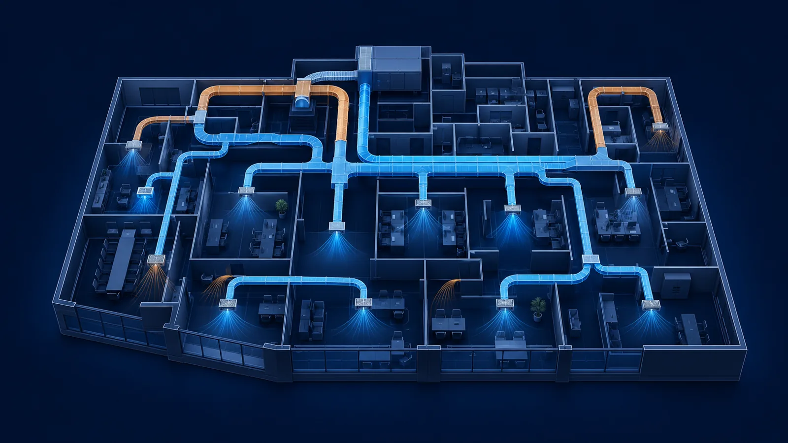
louver sizing calculation
How to Size an Intake or Exhaust Louver: Free Area, Velocity and Pressure Drop
Original MEPFlow engineering guide
Prepared to help mechanical designers understand the calculation, assumptions and review checks. Examples are original and educational; verify the governing code, project criteria and equipment data before using a result for construction or permit documents.
A louver is not an unobstructed wall opening. Its frame, blades, supports and optional screen reduce the area available for air to pass. Dividing airflow by nominal width and height therefore gives face velocity, not the higher velocity through the actual openings.
A useful louver sizing calculation starts with design airflow, estimates required free area, and then replaces that estimate with data for an actual manufacturer size. The final review also covers pressure drop, flow direction, water performance, accessories and installation. This guide shows the workflow without treating one velocity as a universal limit.
The louver sizing equations
Free area is the portion of the louver face through which air can pass after blade and frame restrictions are removed. Manufacturer tables normally report it for each width and height. Greenheck's selection guidance notes that the percentage can change with size, so a value for a standard test specimen should not automatically be applied to every dimension.
For preliminary sizing, select a documented free-area velocity appropriate to the project and product type. Divide airflow by that velocity. Once a candidate model is chosen, use its exact catalog free area and recalculate the operating velocity.
Engineering visual
From airflow to a reviewed selection
Design airflow
CFM or m³/s
Required free area
Q ÷ target velocity
Catalog size
Exact published free area
Final checks
ΔP + rain + accessories
A_free = Q ÷ V_free and V_free = Q ÷ A_free
Use Q in CFM and V_free in FPM to obtain A_free in square feet. In SI units, m³/s divided by m/s gives square metres.
| Quantity | Calculation | Purpose |
|---|---|---|
| Gross face area | Nominal width × height | Opening coordination and face velocity |
| Free area | Published open area for the model and size | Product airflow review |
| Face velocity | CFM ÷ gross face area | General coordination when clearly labelled |
| Free-area velocity | CFM ÷ actual free area | Pressure-drop and water-performance data |
Worked example: a 6,000 CFM outdoor-air intake
Assume an air-handling unit requires 6,000 CFM of outdoor air. For screening, the designer selects 600 FPM free-area velocity and assumes a 45% free-area ratio. These are example assumptions, not universal limits or certified product data.
Required free area is 6,000 ÷ 600 = 10.0 ft². Dividing by the assumed ratio gives an estimated gross area of 10.0 ÷ 0.45 = 22.2 ft². A square opening would be about 56.6 inches per side, so a 60 by 60 inch nominal louver is a logical catalog size to investigate.
That opening has 25.0 ft² gross area. At the preliminary 45% ratio, free area is 11.25 ft² and velocity is 6,000 ÷ 11.25 = 533 FPM. The same values are approximately 2.83 m³/s, 1.05 m² and 2.71 m/s.
Now replace the assumption. If the selected manufacturer's table reports 10.8 ft² of free area for the exact model and size, the reviewed velocity becomes 556 FPM. Read intake pressure drop and water performance at that point, then confirm that the wall opening and accessories match the evaluated configuration.
6,000 CFM ÷ 600 FPM = 10.0 ft² required free area
At an assumed 45% free-area ratio, estimated gross area is 22.2 ft². Replace that ratio with exact catalog data before selection.
Free-area percentage is only a screening input
Frames and blades affect sizes differently. Recalculate using the published free area for the exact width, height, model and section arrangement.
Pressure drop completes the airflow check
Louvers with similar free area can have different resistance because blade depth, spacing and geometry differ. Read the manufacturer's tested pressure-drop curve at the calculated velocity and in the correct airflow direction. Add the loss to the fan's external static-pressure path instead of assuming it is negligible.
Check the complete assembly. Screens, control dampers, filters, plenum transitions and rain-management components can add resistance. Confirm whether each accessory was present in the published configuration; otherwise obtain separate data or an assembled selection from the manufacturer.
- Use intake data for an intake and exhaust data for an exhaust opening.
- Check maximum scheduled airflow and relevant part-load operation.
- Carry louver loss into the fan schedule and critical duct path.
- Do not use velocity alone as proof of acceptable fan performance.
Still-air water penetration is not wind-driven-rain performance
AMCA 500-L provides laboratory methods used to rate several aspects of louver performance. Traditional beginning-point-of-water-penetration data describes a still-air test. Greenheck explains that the test uses free-falling rain without simulated wind, so its result should not be read as severe-storm performance.
Wind-driven-rain products are evaluated under different conditions and can trade lower free area or higher pressure drop for better water rejection. When severe weather applies, review the specified test method, product configuration and project criteria. AMCA also notes that passing its high-velocity wind-driven-rain test does not mean a louver is completely watertight.
Compare operating velocity with the selected product's published water data and provide a path for any water that enters. Flashing, sill pans, drainable plenums and separation from moisture-sensitive equipment remain part of the installation review.
| Design question | Evidence |
|---|---|
| How much air? | Maximum scheduled intake or exhaust CFM |
| What is the restriction? | Size-specific free-area table |
| Can the fan overcome it? | Correct-direction pressure-drop curve |
| What exposure applies? | Relevant water or wind-driven-rain data |
| What changes the assembly? | Screens, dampers, mullions and installation details |
A repeatable selection workflow
Keep the calculation connected to the product schedule so later airflow and architectural changes are easy to review. Project-specific requirements should replace every preliminary assumption before construction documents are issued.
1. Establish airflow and function
Record maximum coincident CFM, intake or exhaust direction, exposure and required accessories.
2. Estimate free area
Divide airflow by a documented preliminary free-area velocity.
3. Choose candidate dimensions
Use a clearly labelled screening ratio to estimate face size.
4. Replace assumptions
Read exact free area for each candidate model, size and multi-section arrangement.
5. Check performance
Recalculate velocity, read pressure drop and review the relevant water data.
6. Coordinate installation
Confirm opening dimensions, screens, dampers, drainage, structure and fan pressure allowance.
Common mistakes and the connected HVAC path
Frequent errors include calling face velocity free-area velocity, applying one free-area percentage to every size, selecting on velocity without checking pressure drop, using exhaust data for an intake, treating still-air water data as wind-driven-rain performance, and ignoring accessories or mullions.
The selected louver is one component in the complete air path. Carry its tested pressure loss alongside duct friction, fittings, dampers, filters, coils and terminals. MEPFlow's duct workflow can organize those connected quantities, while the free diffuser and grille sizing calculator provides a quick area-and-velocity check during preliminary coordination.
The final schedule should identify the selected model or performance basis, design airflow, free area, pressure drop, water-performance basis, accessories and installation details so another engineer can review the selection.
Frequently asked questions
How do you calculate required louver free area?
Divide design airflow by the selected free-area velocity. For example, 6,000 CFM divided by 600 FPM requires 10.0 ft². Then verify the exact free area of a real product size.
What is the difference between face velocity and free-area velocity?
Face velocity uses gross nominal area. Free-area velocity uses the smaller open area after frames and blades are deducted, so it is higher at the same airflow.
Can every louver use the same free-area percentage?
No. A percentage helps with early screening, but free area changes with model and dimensions. Use the manufacturer's table for the exact selected size.
What louver pressure drop should be used?
Use tested data for the selected model at its operating point and correct flow direction. Include accessory losses when they are outside the published configuration.
Is still-air water penetration the same as wind-driven-rain performance?
No. They represent different test conditions. Review the rating appropriate to the project's exposure and do not interpret either as a guarantee that no water can enter.
Continue the engineering workflow
Put this guide into practice with MEPFlow
Move from the calculation method into a connected browser-based design workflow while keeping the assumptions visible for engineering review.
Explore HVAC duct design softwarePrimary references
Use the edition and method accepted for your project. These authoritative resources provide further context; this article is educational and is not a code-compliance determination.