How to Size a Domestic Hot-Water Recirculation System
Recirculation flow replaces distribution heat loss; it is not the same as peak fixture demand or the building's domestic hot-water load.
Heat loss → flow → head
How to Size a Domestic Hot-Water Recirculation System
Original MEPFlow engineering guide
Prepared to help mechanical designers understand the calculation, assumptions and review checks. Examples are original and educational; verify the governing code, project criteria and equipment data before using a result for construction or permit documents.
A domestic hot-water recirculation system keeps the distribution network near its target temperature so occupants do not wait for cooled water to be purged. The required recirculation flow is based primarily on distribution heat loss and the allowable supply-to-return temperature drop.
Peak fixture demand sizes the hot-water supply branches and source capacity. Recirculation flow is a separate operating condition and is usually much smaller. Mixing the two leads to oversized pumps, excessive velocity and avoidable heat loss.
Heat loss sets recirculation flow
Estimate heat loss from the active hot-water distribution segments using pipe size, insulation, ambient temperature and length. Divide that heat loss by the heat carried per unit flow across the selected recirculation temperature drop.
For water in I-P units, the common approximation is GPM = Btu/h ÷ (500 × ΔT°F). Use temperature-dependent fluid properties when the application requires greater precision.
Engineering visual
The recirculation design loop
Heater
Supply temperature
Hot water enters the distribution main
Distribution
Heat loss
Insulated pipe loses heat to surrounding spaces
Return pump
Restore temperature
Flow returns cooled water to the source
Recirculation GPM ≈ distribution heat loss ÷ (500 × ΔT)
A 20,000 Btu/h loop with a 10°F design drop requires about 4 GPM of recirculation flow.
Assign flow through branches
A large recirculation network needs a method to allocate total flow among return branches. Heat-loss proportional balancing assigns more flow to branches losing more heat. Circuit setters, balancing valves or pressure-independent devices are then selected to establish the intended distribution.
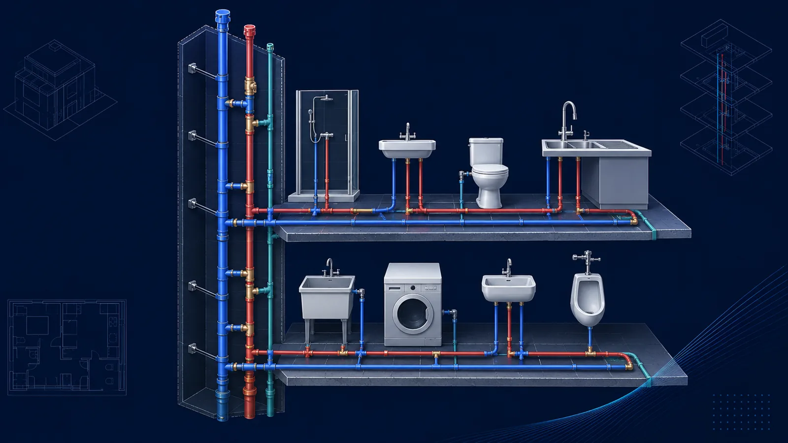
Every remote branch needs a viable return path. A floor-plan network helps reveal dead ends and branches that would otherwise wait for hot water.
Size the return piping
Return pipe is sized from recirculation flow, velocity and friction criteria—not from fixture units. Very small pipe can create high friction and balancing difficulty; oversized return pipe increases water volume, cost and heat-loss surface.
Velocity limits may be more restrictive for continuous hot-water recirculation because high velocity, temperature and water chemistry can contribute to erosion-corrosion. Follow project and material guidance.
Select pump flow and head
Pump flow is the design recirculation rate. Pump head is the friction loss around the hydraulically critical closed loop: supply path to the branch connection plus return path back through valves and equipment.
Do not add building elevation as ongoing pump head around a closed loop. The pump must overcome friction, while the static fill pressure establishes adequate pressure throughout the system.
1. Calculate pipe heat loss
Use actual lengths, insulation and ambient conditions.
2. Select loop ΔT
Choose the allowable distribution temperature drop.
3. Calculate and allocate flow
Convert heat loss to total GPM and distribute it among branches.
4. Size returns and balancing devices
Check velocity, friction and controllability.
5. Calculate the critical loop
Add supply, return, valve and equipment losses for pump head.
Controls and energy
Continuous recirculation increases pipe heat loss and pump energy. Temperature, time, occupancy or demand-based controls can reduce operation when allowed by the system's health, service and code requirements.
Keep return temperatures, storage temperatures, mixing arrangements and microbial-control strategy coordinated. Recirculation is both a comfort and water-management system.
Worked recirculation flow and pump-head example
Suppose the calculated heat loss from a domestic hot-water supply loop is 12,000 Btu/h and the design permits a 10°F temperature drop between the heater supply and the return. For water, the familiar approximation GPM = Btu/h ÷ (500 × ΔT) gives 2.4 GPM. This is the total recirculation flow required to replace distribution heat loss; it is not the peak fixture draw and should not be sized from water-supply fixture units.
Assign the 2.4 GPM through the actual return network according to the heat loss of each branch. A long or poorly insulated remote branch may need a greater share than a short nearby branch. After flows are assigned, size the return piping and calculate the complete pump path from the pump through the supply main, controlling branch and return main. If pipe and fitting loss is 7 ft, balancing devices add 4 ft, and the heater/check-valve path adds 5 ft, the design pump point is 2.4 GPM at 16 ft of head before a justified allowance.
Because the loop is closed, static elevation does not add to operating pump head after the system is full; elevation gains and losses cancel around the circuit. The pump overcomes friction and device losses. Elevation still matters for fill pressure, air management and component pressure ratings, but it should not be added as a one-way lift to the recirculation pump calculation.
| Input | Value |
|---|---|
| Distribution heat loss | 12,000 Btu/h |
| Permitted loop temperature drop | 10°F |
| Required recirculation flow | 2.4 GPM |
| Pipe and fitting loss | 7 ft |
| Balancing-device loss | 4 ft |
| Heater and valve loss | 5 ft |
| Preliminary pump point | 2.4 GPM at 16 ft |
Balance, control and verify the operating loop
Without balancing, the closest return path can take most of the flow while remote branches remain cool. Manual balancing valves can work when loads are stable and commissioning is thorough. Thermostatic balancing valves can adjust branch flow in response to temperature, but their minimum pressure-drop and temperature characteristics must be included in pump selection.
Continuous high-speed circulation wastes pump energy and increases pipe heat loss. It can also accelerate erosion in small return piping. Controls may use time schedules, temperature sensors, demand activation or combinations suited to the occupancy and code requirements. The control sequence must still maintain required temperatures and any applicable pathogen-control strategy.
Commissioning should measure supply and return temperatures at the heater and representative remote branches after the system stabilizes. Record balancing-valve positions, pump speed and differential pressure. If temperatures are poor, verify insulation continuity, check-valve direction, cross connections, branch flow and sensor placement before simply increasing pump speed.
- Calculate flow from distribution heat loss and allowable temperature drop.
- Allocate branch flows by branch heat loss, not equal flow by default.
- Include balancing-valve, check-valve and heater losses in the pump path.
- Use actual return-pipe inside diameters and review velocity at the small design flow.
- Document the operating schedule and commissioning temperature criteria.
Frequently asked questions
Is recirculation flow based on fixture units?
No. Fixture units estimate probable fixture demand. Recirculation flow is generally based on distribution heat loss and allowable loop temperature drop.
Do I include building height in recirculation pump head?
Not as ongoing head around a closed loop. Pump head is based on loop friction and component losses, while system fill pressure handles static elevation.
Why balance recirculation branches?
Without balancing, low-resistance branches can take excess flow while remote or high-resistance branches remain too cool.
Primary references
Use the edition and method accepted for your project. These authoritative resources provide further context; this article is educational and is not a code-compliance determination.