Pipe Volume Calculator Formula: Gallons, Litres and System Volume
Pipe volume is simple geometry, but using nominal instead of actual inside diameter can distort expansion-tank, glycol and fill-volume calculations.
V = πD²L ÷ 4
Pipe Volume Calculator Formula: Gallons, Litres and System Volume
Original MEPFlow engineering guide
Prepared to help mechanical designers understand the calculation, assumptions and review checks. Examples are original and educational; verify the governing code, project criteria and equipment data before using a result for construction or permit documents.
Pipe volume is the internal cross-sectional area multiplied by pipe length. Engineers use it to estimate fill volume, glycol quantity, expansion-tank acceptance, chemical treatment and the active thermal mass of hydronic systems. The arithmetic is straightforward; the common errors are diameter, units and missing equipment volume.
Always use actual inside diameter for the selected material and schedule. Nominal pipe size is a name, not a measurement. Two products with the same nominal size can contain different volumes per foot or metre.
The pipe volume formula
For a circular pipe, area is πD²/4 and volume is area multiplied by length. If diameter and length are both in feet, the result is cubic feet; multiply by 7.4805 to obtain US gallons. If dimensions are in metres, the result is cubic metres; multiply by 1,000 to obtain litres. Keep diameter in the same base unit as length before applying the formula.
A convenient IP form is gallons = 0.0408 × inside diameter² in inches × length in feet. The coefficient includes the inch-to-foot conversion and gallons per cubic foot. In SI, litres = 0.7854 × inside diameter² in millimetres × length in metres ÷ 1,000. These shortcuts are only as accurate as the inside diameter supplied.
For an annular space or tube bundle, use the actual free area rather than the simple full-circle formula. For tanks and equipment, use manufacturer fluid-volume data whenever available.
Volume = (π × D² ÷ 4) × length
D is actual inside diameter. Convert the resulting cubic volume to gallons or litres only after the geometry uses consistent base units.
Worked gallon and litre examples
A 100 ft run with an actual inside diameter of 2.067 inches contains approximately 0.0408 × 2.067² × 100 = 17.4 US gallons. If someone uses a nominal 2.0-inch diameter instead, the estimate is 16.3 gallons—about six percent low. Across hundreds of feet and multiple sizes, the difference can materially affect glycol purchase and expansion volume.
For an SI example, a 40 m pipe with 52.5 mm inside diameter contains 0.7854 × 52.5² × 40 ÷ 1,000 = about 86.6 litres. Add the volume of every branch rather than multiplying one representative size by total system length.
A spreadsheet or connected model should group quantities by material, schedule and size. This makes the assumed inside diameter auditable and simplifies updates when a portion of the network changes size.
| Inside diameter | Length | Calculated volume |
|---|---|---|
| 2.067 in | 100 ft | 17.4 US gal |
| 2.000 in used incorrectly | 100 ft | 16.3 US gal |
| 52.5 mm | 40 m | 86.6 L |
Build a complete system-volume inventory
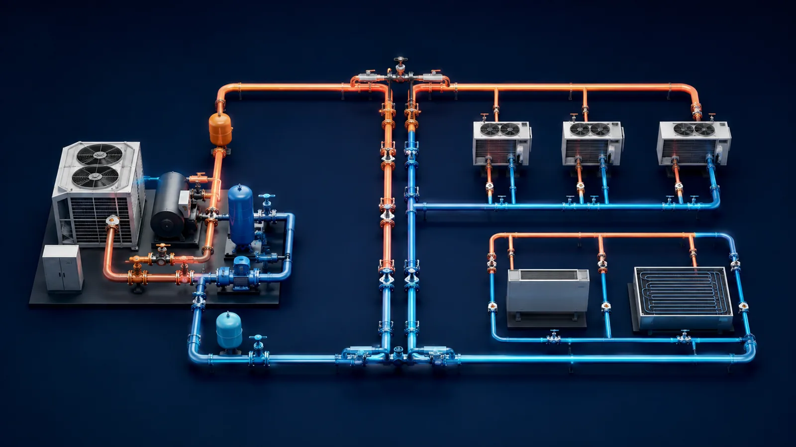
Pipe volume is only one part of a hydronic system. Add boilers, chillers, heat pumps, coils, heat exchangers, air separators, headers and buffer tanks. Manufacturer data is preferable to estimating complex equipment geometry. Include future connected sections only if the design must accommodate them from day one.
For expansion-tank sizing, apply fluid expansion to the complete connected volume. For glycol procurement, include an allowance for the fill and purge process while avoiding excessive waste. For buffer-tank analysis, distinguish total system volume from the smaller volume that remains active during the controlling low-load condition.
Preserve the inventory with the calculation. A single unexplained total is difficult to review and easy to understate when equipment changes. A table of size, inside diameter, length and volume turns the number into a maintainable project record.
- Use actual inside diameter from the selected pipe or tube standard.
- Keep all dimensions in consistent units before converting volume.
- Sum each size and branch rather than using one average diameter.
- Add manufacturer fluid volumes for equipment and tanks.
- State whether the total is used for expansion, glycol fill or active thermal mass.
Use pipe volume for expansion, glycol and thermal-mass decisions
The same system-volume inventory supports several calculations, but each uses it differently. Expansion-tank sizing applies the fluid's expansion fraction between the cold fill and maximum average temperature, then divides required acceptance by the tank's pressure-dependent acceptance factor. The tank is not selected by system gallons alone. Glycol procurement multiplies total fill volume by the specified concentration convention and should include the mixing and purge plan.
Thermal-mass calculations use only volume that is hydraulically active during the controlling operating condition. If zone valves isolate most branches while a heat pump serves one small zone, total installed volume can greatly exceed active volume. A buffer-tank calculation must therefore identify connected pipe and equipment that remain in circulation when the minimum load occurs.
Pipe takeoff also supports flushing and chemical treatment. Large systems may need temporary flow rates and equipment that differ from normal operation. A transparent inventory helps estimate water disposal, inhibitor quantity and sampling points. Keep construction changes synchronized because a late buffer tank, larger header or revised pipe schedule can materially change the total.
For quality control, compare the detailed volume against a rough length-and-size summary, but do not replace the detailed calculation with a generic gallons-per-ton assumption. Two systems with the same capacity can have very different distribution volume. The physical network and equipment list are the reliable basis.
| Purpose | Volume basis | Additional input |
|---|---|---|
| Expansion tank | All connected fluid | Temperature expansion and pressure acceptance |
| Glycol fill | All fluid to be mixed | Concentration convention and purge allowance |
| Buffer analysis | Active minimum-load volume | Source output, load, runtime and usable ΔT |
| Chemical treatment | Treatable connected volume | Product dosage and water quality |
Frequently asked questions
How do I calculate gallons in a pipe?
For inside diameter in inches and length in feet, gallons are approximately 0.0408 × diameter² × length.
Should I use nominal pipe size?
No. Use actual inside diameter for the material and schedule because nominal size can differ materially from the free bore.
Does pipe volume equal total system volume?
No. Add fluid contained in boilers, chillers, coils, heat exchangers, tanks, headers and other connected equipment.
Primary references
Use the edition and method accepted for your project. These authoritative resources provide further context; this article is educational and is not a code-compliance determination.