How to Calculate Air Velocity in a Duct from CFM
Use airflow and free area to calculate FPM or m/s, then understand why an acceptable velocity still does not prove the duct system is properly sized.
V = CFM ÷ A
How to Calculate Air Velocity in a Duct from CFM
Original MEPFlow engineering guide
Prepared to help mechanical designers understand the calculation, assumptions and review checks. Examples are original and educational; verify the governing code, project criteria and equipment data before using a result for construction or permit documents.
Duct velocity is airflow divided by internal free area. It is one of the quickest checks in air-distribution design because it connects the assigned CFM to the physical size of the duct. Velocity affects noise, fitting loss, throw, transport and the amount of ceiling space required.
Velocity is not a complete sizing method by itself. Two ducts with acceptable FPM can have very different friction rates, fitting losses and critical-path pressure requirements.
The velocity formula
For I-P calculations, divide CFM by internal area in square feet to obtain feet per minute. For SI calculations, divide cubic metres per second by square metres to obtain metres per second.
Use the actual internal dimensions. Liner, internal reinforcement and manufacturing tolerances can reduce free area when they are significant.
Engineering visual
Airflow, area and velocity
Airflow
Q
CFM or m³/s assigned to the segment
Free area
A
Internal cross-sectional area
Velocity
V = Q/A
FPM or m/s through the duct
Velocity (fpm) = airflow (CFM) ÷ area (ft²)
For a rectangular duct, area is width × height. For a round duct, area is πD²/4 after converting diameter to feet.
Worked round-duct example
A 16-inch round duct has a diameter of 1.333 feet and an area of approximately 1.396 square feet. At 1,000 CFM, velocity is approximately 716 fpm.
If the same airflow is forced through a 12-inch round duct, area falls to 0.785 square feet and velocity increases to about 1,274 fpm. The smaller duct may fit more easily but creates a different friction, noise and fitting-loss condition.
| Diameter | Area | Velocity |
|---|---|---|
| 12 in | 0.785 ft² | 1,274 fpm |
| 14 in | 1.069 ft² | 936 fpm |
| 16 in | 1.396 ft² | 716 fpm |
Rectangular duct and aspect ratio
A 12 × 12 inch duct has one square foot of area, so 1,000 CFM produces 1,000 fpm. A 24 × 6 inch duct has the same gross area and velocity, but more perimeter and a less favourable aspect ratio.
Equal area does not mean equal friction or cost. Rectangular equivalence relationships account for shape, and project criteria often limit aspect ratio for constructability and performance.
How to choose a velocity limit
Appropriate velocity depends on duct location, acoustics, system type and available pressure. A main duct in a mechanical room can tolerate conditions that may be unsuitable above a quiet meeting room. Use the project design criteria and recognized duct-design guidance.
- Check velocity at terminals and near sound-sensitive spaces.
- Review fittings where local velocity pressure converts into loss.
- Check return and exhaust systems separately from supply.
- Confirm that automatic sizing respects both friction and velocity constraints.
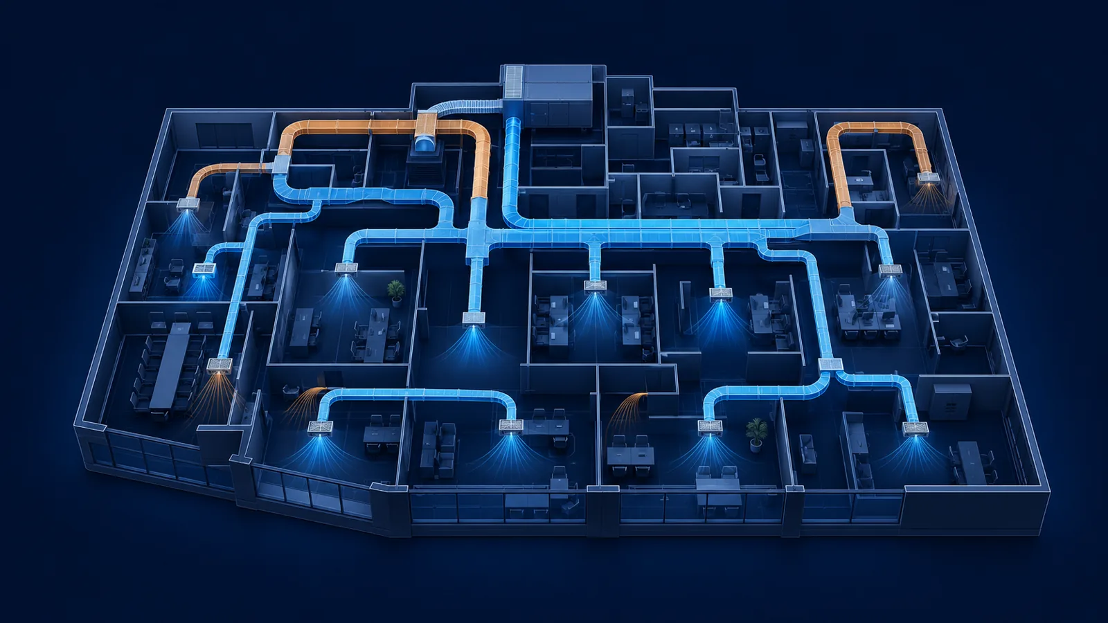
Follow velocity as airflow accumulates through a duct network
Velocity is a segment property, so it must be recalculated whenever airflow or area changes. Four diffusers at 250 CFM each may connect to 8-inch branches, but the upstream trunk carries 1,000 CFM. If that trunk were also 8 inches round, its area would be about 0.349 ft² and velocity would approach 2,865 fpm—usually far above a quiet low-pressure branch criterion. A 14-inch round trunk has about 1.069 ft² of area and carries the same airflow at roughly 935 fpm.
Rectangular sizes must use actual inside dimensions. A nominal 12 by 8 duct has 0.667 ft² gross area and carries 1,000 CFM at 1,500 fpm. Internal liner reduces the free dimensions and increases velocity. A two-inch overall reduction in both width and height produces a 10 by 6 free opening, only 0.417 ft², and velocity rises to about 2,400 fpm. That difference affects friction, noise and fitting performance.
The network view also exposes abrupt velocity changes. A transition can be necessary when branches join, but a short or poorly proportioned transition can create separation and additional pressure loss. Displaying airflow, size and velocity together makes it easier to identify segments that need a different dimension, aspect ratio or transition length.
| Duct | Free area | Velocity |
|---|---|---|
| 8 in round | 0.349 ft² | 2,865 fpm |
| 14 in round | 1.069 ft² | 935 fpm |
| 12 × 8 in rectangular | 0.667 ft² | 1,500 fpm |
| 10 × 6 in free area after liner | 0.417 ft² | 2,400 fpm |
Velocity limits must be coordinated with friction and acoustics
A velocity limit by itself does not establish pressure drop. Two ducts at the same velocity can have different hydraulic diameters, roughness and fitting losses. Conversely, an equal-friction sizing method can produce different velocities as airflow changes. Good design reviews both criteria and then calculates the complete path through terminals, fittings, accessories and equipment.
Location matters. A short main duct inside a mechanical room may tolerate a higher velocity than a branch above a quiet boardroom. Return-air openings and transfer paths require face-velocity review because generated noise occurs at grilles and restrictions, not only in sheet metal. Systems with variable airflow must also be checked at minimum operation, when diffuser throw and control stability can become the limiting conditions.
Do not treat general velocity ranges as code limits. Establish project-specific criteria from acoustical goals, duct construction, available pressure, equipment data and applicable standards. Record the reason for exceptions. A high-velocity shaft riser can be entirely intentional if pressure, sound and leakage are addressed; an accidental high-velocity branch near a diffuser is a different situation.
- Calculate velocity from free internal area after liner or obstructions.
- Review main, branch, terminal neck and grille face velocities separately.
- Check transitions and fittings where velocity changes abruptly.
- Evaluate both design airflow and minimum variable-air-volume operation.
- Use the critical-path pressure calculation to confirm that the velocity choice fits the fan budget.
Frequently asked questions
How do I convert CFM to duct velocity?
Divide CFM by the duct's internal cross-sectional area in square feet. The result is feet per minute.
What is the area of a round duct?
Area is πD²/4. Convert diameter to feet before using the result with CFM and fpm.
Can I size ductwork using velocity alone?
No. Also review friction rate, fitting and component losses, noise, critical-path pressure and constructability.
Primary references
Use the edition and method accepted for your project. These authoritative resources provide further context; this article is educational and is not a code-compliance determination.